
A semi-comprehensive guide to the machines in the AB workshop.
A Guide to Our Workshop’s MachinesCNCsGantry CNC MillTormach CNC MillMini CNC MillSawsChop SawBand SawJig SawRail SawCold SawLatheDrill Press3D Printers
CNCs
CNC (“Computer Numerical Control”) manufacturing is the automated use of machining tools to transform a piece of material through a set of very precise instructions. These machines usually have a drill bit and a platform with the material to be cut, although they differ in purpose and usage.
Gantry CNC Mill
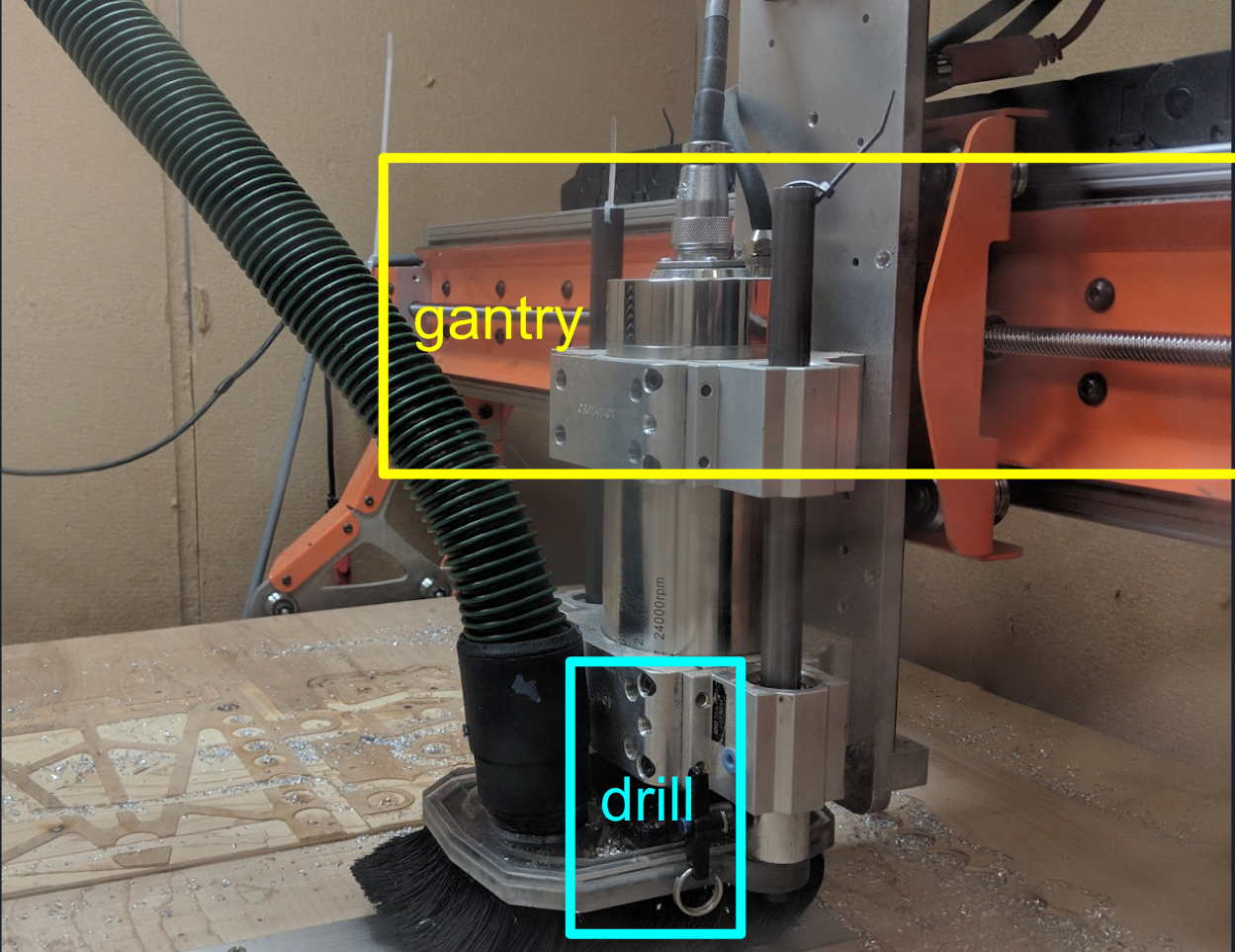
- A gantry mill is used to cut thin sheets of soft material like wood or aluminum.
- The gantry mill is equipped with a vacuum that clears away removed scraps of material, preventing bits of material from getting caught in the machine. This also reduces the friction and thus the heat generated by the gantry mill to some extent, but the gantry mill is still not equipped for overly strenuous tasks.
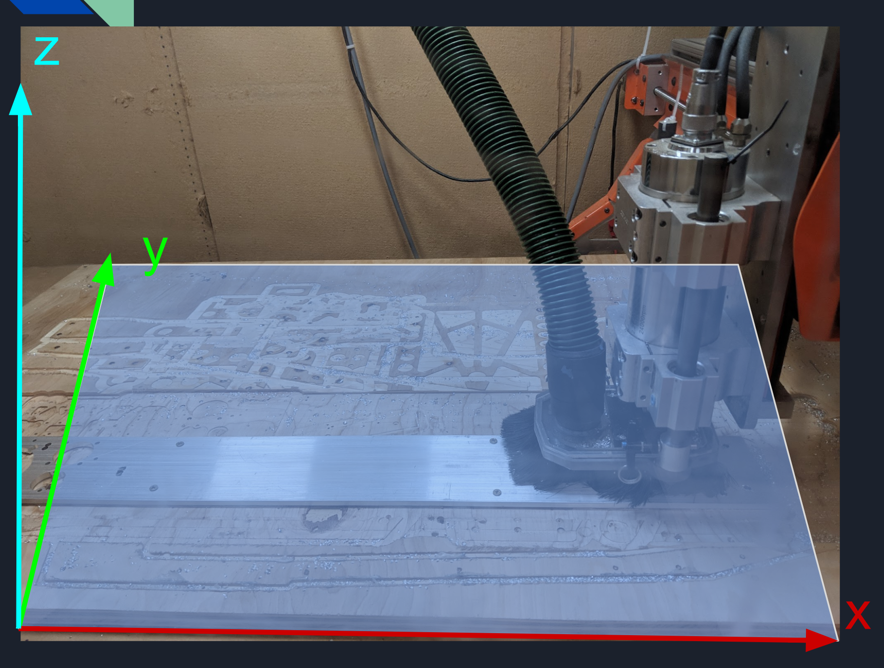
- The gantry mill is used by loading in CAM (Computer Aided Manufacturing) files, which can be generated from CAD files through the CAM tab in Autodesk Inventor. CAM creates g-code, a set of precise instructions for the mill denoting how to create the desired 3D shape. These files specify the movement of the drill bit on the XYZ cartesian plane that the gantry mill operates on.
- When the CAM files are loaded into the gantry mill, the gantry moves the drill or mill bit around the x, y, or z-axes in the enclosure, moving the drill bit up and down (changing the Z coordinate) to cut material off the sheet.
Tormach CNC Mill
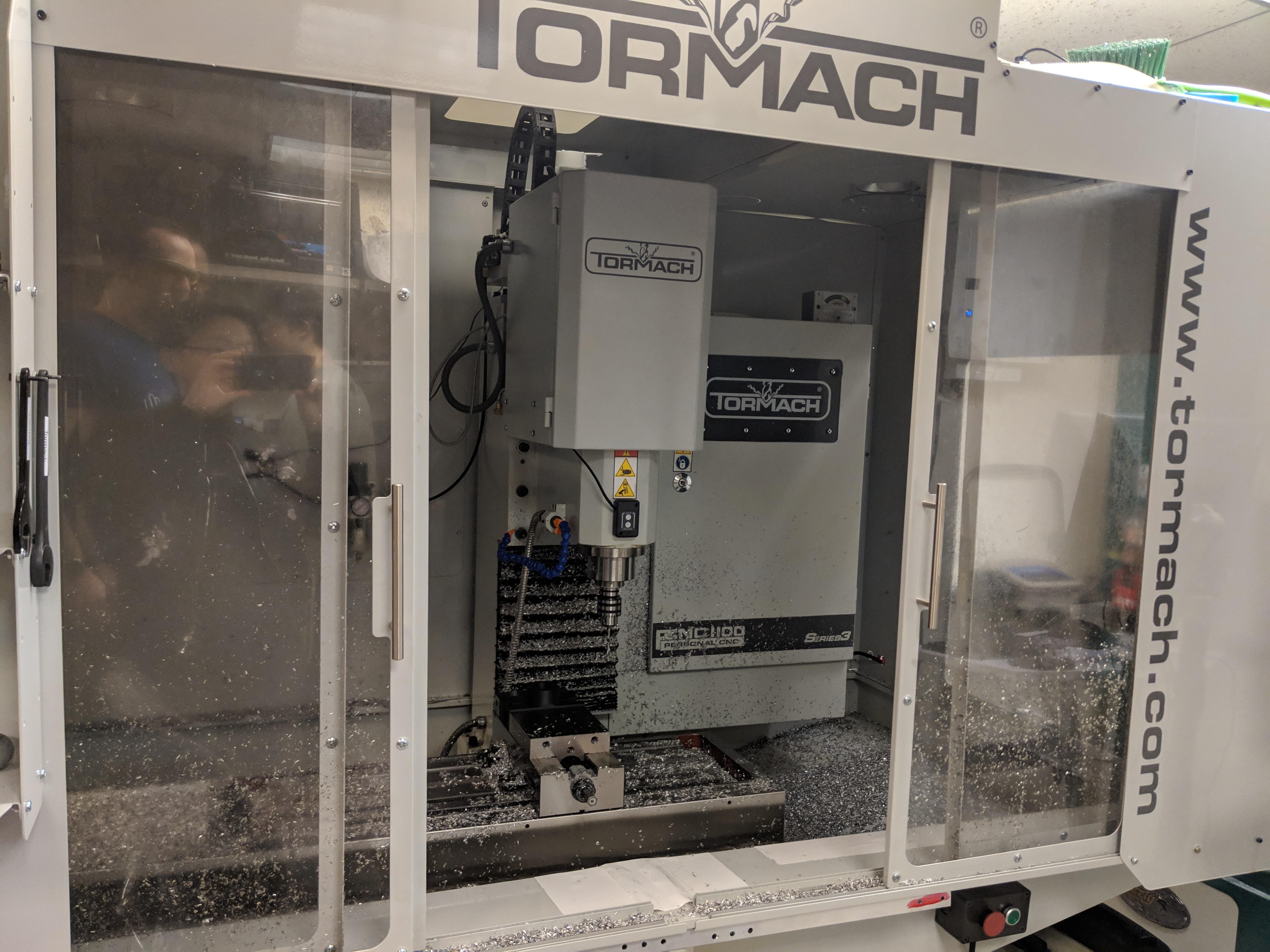
- The Tormach CNC mill is used to cut blocks of hard materials like steel.
- Unlike the gantry mill, the Tormach CNC mill is equipped with a cooling system, where both the material and the drill bit is covered with coolant while a program is in progress. This is a fairly efficient process, which allows the Tormach CNC mill to accomplish strenuous tasks.
- The Tormach CNC mill is also used by loading in CAM (Computer Aided Manufacturing) files, which can be generated from CAD files through the CAM tab in Autodesk Inventor. These files specify the movement of the drill bit on the XYZ cartesian plane that the gantry mill operates on.
- In contrast to the gantry mill, the Tormach CNC mill moves the material being cut while holding the drill or mill bit stationary. The drill bit in the Tormach CNC mill is connected to one enormous and heavy piece of metal going through the entire structure of the mill, so the drill bit is incapable of movement. This lends a greater stability to the Tormach CNC mill compared to the gantry mill, while allowing for greater motion in the z-axis to create parts with greater depth.
Mini CNC Mill
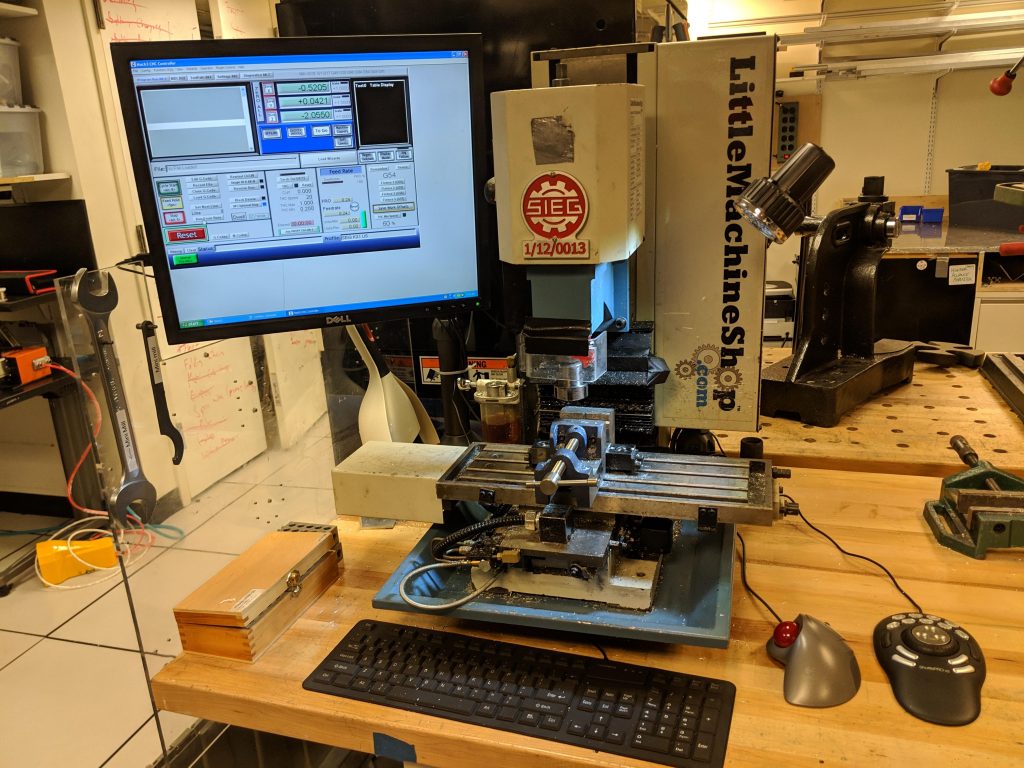
- The mini CNC mill is used for cutting metals (such as aluminum) down to specific lengths with incredible precision, often after a part is rough cut by the chop saw.
- The mini CNC mill is manually controlled through the use of a keyboard. The platform with the material is moved across x, y, and z-axes while the bit is held stationary like in the Tormach CNC mill. Parameters such as the speed of the material’s movement and the speed of the bit’s rotation can also be changed.
- Unlike the gantry mill and Tormach CNC mill, the mini CNC mill is manually operated and does not use CAM.
Saws
Chop Saw
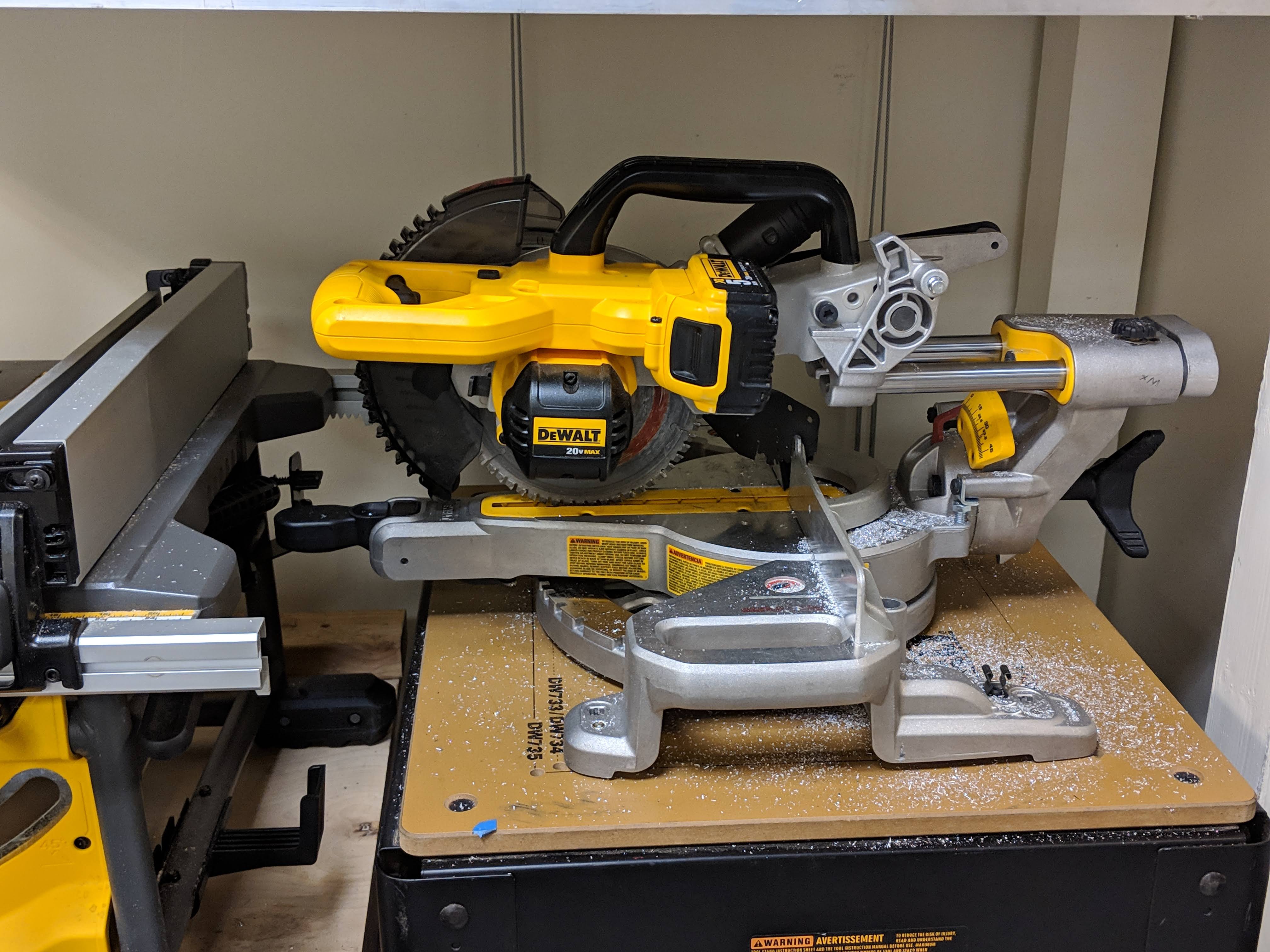
- The chop saw is used for rough cutting materials. Although it is used mostly for wood, it can also be used with aluminum.
- When the chop saw is turned on, a circular blade spins very quickly and is manually lowered and pushed into the material.
Band Saw
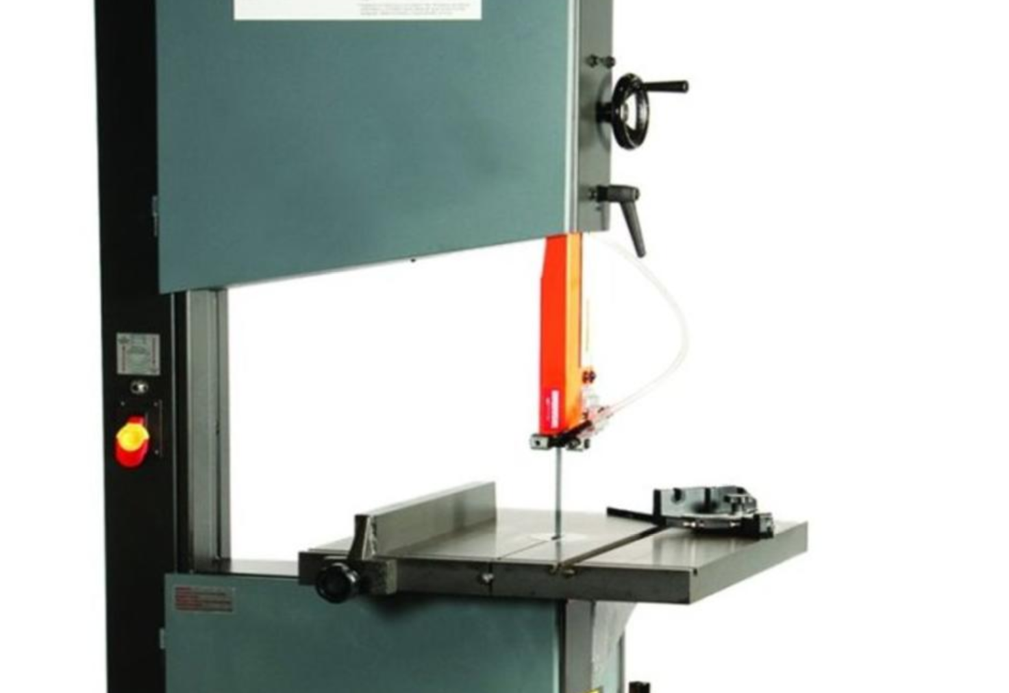
- The band saw is used to make longer cuts in many different materials, with different speeds for different materials.
- When the band saw is turned on, a vertical blade moves up and down at a high speed. Material is pushed manually into the moving saw, usually against a straight edge for balance.
- The band saw gets very hot, so wear gloves!
Jig Saw
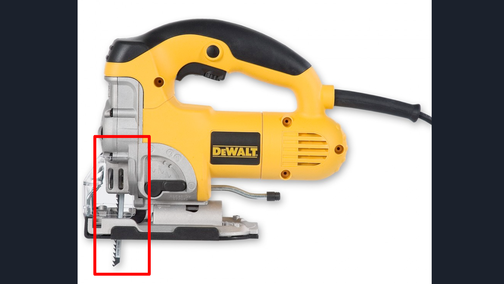
- The jig saw is used like a portable band saw.
- When the jig saw is turned on, the blade moves quickly up and down. The saw is then manually moved through the material to cut it. As a handheld saw, it can be rather difficult to use.
- It is possible for the blade to snap. Protect your fragile little fingers.
Rail Saw
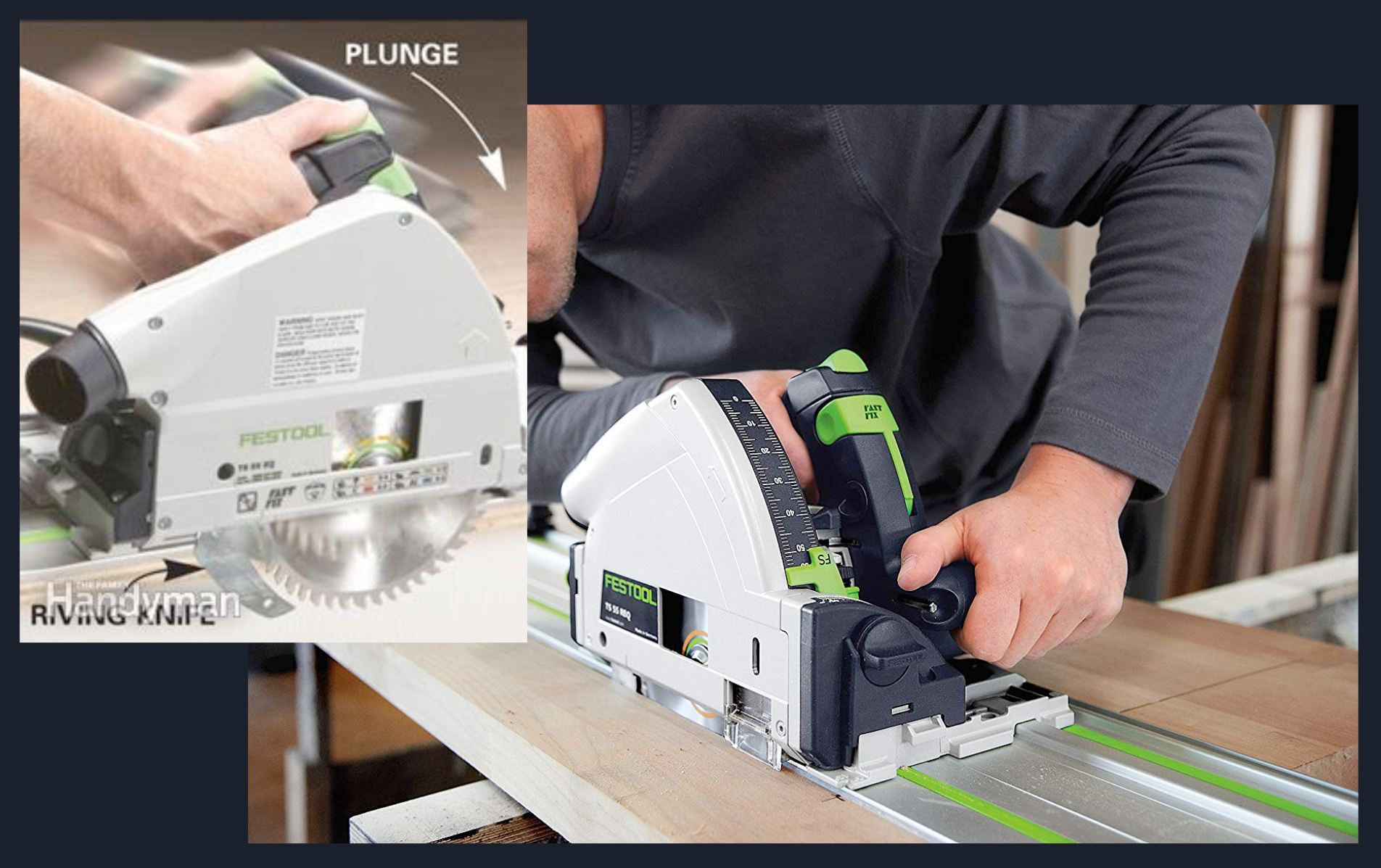
- The rail saw is used to make extremely long cuts in a straight line, especially when cutting up large plywood or metal sheets.
- When the rail saw is turned on, a set of circular blades spin very fast. The saw is then pushed manually downwards and across the material. The saw is mounted onto a set of rails that it can slide up and down on, allowing it to cut materials across a straight line.
Cold Saw

- The cold saw is used for accurately cutting metal extrusions or parts. The cooling fluid that is used during cuts allows the metal and the saw to remain cool and lubricated, making the cold saw the best saw for cutting metal.
- When the cold saw is turned on, a circular blade spins very quickly and is manually lowered and pushed into the material, much like the chop saw.
Lathe
The lathe spins a shaft and uses a blade to cut material off or drill a hole.
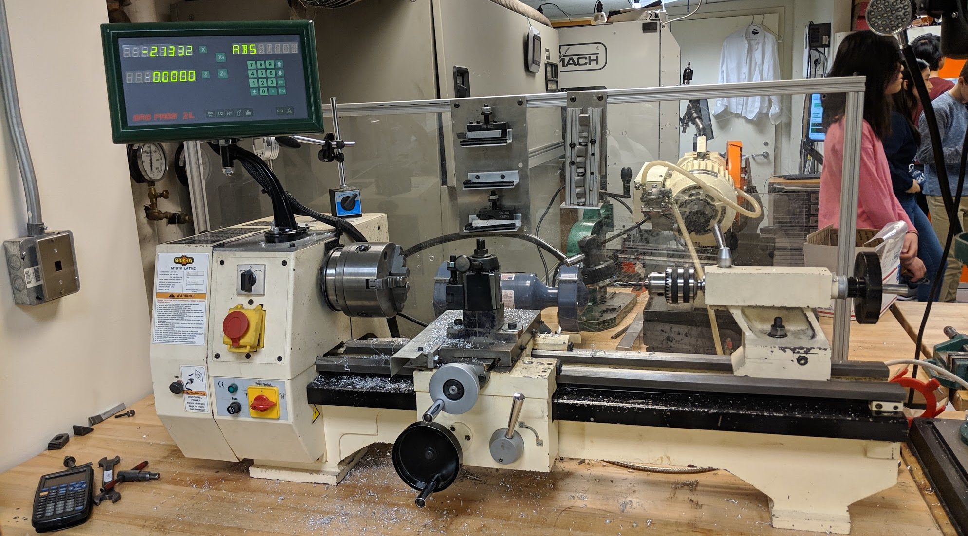
- The lathe is used to obtain shafts with specific lengths, usually after rough cutting with a chop saw.
- The lathe can also be used to drill especially large holes into shafts.

- To obtain a shaft of a specific length, the shaft is first secured in the spindle. Using the display with the XZ coordinates, zero the blade at the end of the shaft. When the lathe is turned on, the shaft will begin to spin quickly. Using the carriage handwheel to move the blade’s XZ coordinates/location, remove material from the shaft. The coordinates on the display will indicate the amount of material removed.
Drill Press
The drill press drills a precise hole into a material.
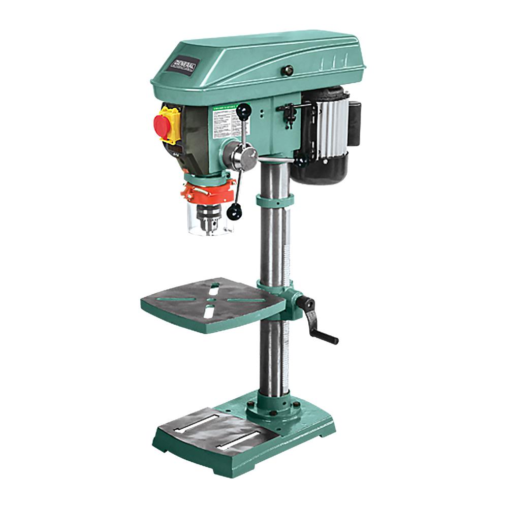
- The drill press is used to drill holes into materials more precisely than with handheld drills.
- Material is mounted on the plate and secured with clamps. The drill bit is aligned with the hole to be drilled, then the red switch is flipped and the lever is pulled.
3D Printers
3D printers can create parts with an incredible range of shapes.

- The 3D printer is used to create parts with near-unlimited configurations of shapes. The relatively simple process of creating a part in a 3D printer makes it handy for rapid prototyping.
- The 3D printer is used by loading in a .stp file exported from a CAD model in Autodesk Inventor. The printer then prints the 3-dimensional shape from the CAD model by building it up in horizontal 2-dimensional layers.
- Although 3D-printed parts are generally inferior in quality to metal parts, the speed of the part creation and the flexibility of part shapes are an advantage. Our 3D printer can print in a variety of materials, including carbon fiber, so the quality of our 3D-printed parts is nevertheless substantial.